Week 01
01.UML as a modeling language
Lesson Outline:
- UML - Overview
- UML - Building Blocks
- UML - Modeling Types
- UML - Basic Notations
01. UML - Overview
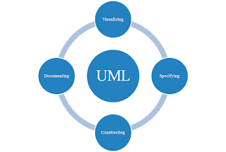
Bound together Displaying Language (UML) is a normalized demonstrating language utilized in programming to imagine, determine, build, and record the curios of a framework. It gives a typical visual portrayal that can be perceived by designers, business examiners, and different partners engaged with the product improvement process. Here is an outline of UML in a bit by bit clarification:
Step 1: Grasping UML
Definition: The software system modeling methodology and set of graphical notations known as UML are used together.
Purpose: It helps in envisioning, planning, and archiving the product design.
Scope: UML can be applied to different kinds of frameworks, including programming frameworks, equipment frameworks, business cycles, and then some.
Step 2: UML Outline Types
UML gives various sorts of graphs to address various parts of a framework:
###Underlying Charts:
- Class Charts: Delineate the static construction of the framework, addressing classes, properties, and connections.
- Object Charts: Show occasions of classes at a specific moment.
- Part Charts: Portray the association and conditions of framework parts.
###Social Outlines:
- Use Case Charts: Depict communications between the framework and outer entertainers.
- Succession Graphs: Address the arrangement of cooperations between objects.
- State Machine Graphs: Delineate the states and state advances of an article.
- Movement Graphs: A system's activity flow can be shown.
- Association Graphs: Correspondence Charts (previously known as Coordinated effort Graphs): Stress the connections between objects.
- Timing Charts: Address the timing limitations of messages.
- Arrangement Graphs: Arrangement Charts: Outline the actual organization of programming parts on equipment hubs.
- Class: Addresses a diagram for objects, characterizing qualities and ways of behaving.
- Object: An example of a class.
- Association: Depicts connections between classes.
- Inheritance: depicts the order in which classes are arranged, with a subclass receiving attributes and behaviors from a superclass.
- Use Case: Addresses a particular cooperation between a framework and an outside substance.
- Activity: Addresses a bunch of activities or tasks.
- State: Addresses a condition during the existence of an item or a cooperation.
- Recognize Prerequisites: Know the system's requirements and the most important parts, interactions, and actions.
- Select Graph Types: Pick the proper UML graphs in view of the perspectives you need to demonstrate (e.g., class charts for structure, grouping outlines for collaborations).
- Design diagrams: Draw diagrams using UML modeling tools and add classes, objects, relationships, and annotations.
- Refine and Repeat: As knowledge of the system grows, the diagrams should be reviewed and improved. Repeat on a case by case basis to catch changes.
- Add notes, remarks, and clarifications to upgrade the comprehension of the outlines.
- Create Documentation: Numerous UML apparatuses offer the choice to create documentation from the models naturally.
- Correspondence: Developers, testers, and project managers can all communicate with one another using UML diagrams as a common language.
- Feedback: In order to enhance the models' accuracy and completeness, encourage collaboration and feedback.
- Update Models: Stay up with the latest as the product develops, guaranteeing they mirror the present status of the framework.
Consider utilizing variant control for UML models to follow changes and corrections.In outline, UML is a flexible and generally involved displaying language that aids the visual portrayal and comprehension of complicated programming frameworks. By following an orderly methodology, partners can use UML to configuration, record, and convey different parts of a framework all through the product improvement lifecycle.
02.UML - Building Blocks
Structural Diagrams:
- Purpose: Address the static design of a framework, zeroing in on classes and their connections.
- Components:
- Class: Addresses a plan for objects.
- Attributes: Properties of a class.
- Methods/Operations: Capabilities or ways of behaving of a class.
- Relationships: Affiliations, speculations, conditions.
- Purpose: Address cases of classes and their connections at a particular moment.
- Components:
- Objects: Cases of classes.
- Links: Associations between objects.
- Purpose: Show the system's components and their dependencies.
- Components:
- Component: A secluded, deployable, and replaceable piece of a framework.
- Interfaces: Characterize correspondence between parts.
- Purpose: Represent the actual installation of software components in hardware settings.
- Components:
- Nodes: Address equipment gadgets or programming execution conditions.
- Artifacts: Address executable records, libraries, or information documents.
Behavioral Diagrams:
- Purpose: Demonstrate how a system and its external entities (actors) interact with one another.
- Components:
- Case Study: Addresses a particular usefulness or errand.
- Actor: Addresses an outside element associating with the framework.
- Purpose: Outline the connections between objects over the long haul.
- Components:
- Lifeline: Addresses the presence of an item over a period.
- Message: demonstrates an interaction between objects.
- Purpose: Show how items team up to accomplish a shared objective.
- Components:
- Objects: Cases of classes.
- Links/Associations: Interface objects.
- Purpose: Model the way of behaving of an item by characterizing its states and advances.
- Components:
- States: Represent conditions throughout an object's lifetime.
- Transitions: Address development between states.
- Purpose: Show how a system's activities move through it.
- Components:
- Movement Hubs: Address assignments or activities.
- Control Stream: demonstrates the execution sequence.
- Purpose: Give an outline of the progression of control among exercises and cooperations.
- Recollect that UML is a flexible language, and the selection of charts relies upon the parts of the framework you need to stress. Joining various kinds of graphs can give an extensive perspective on a product framework.


No comments:
Post a Comment